
Liner and seal
Use the liner guide to separate cosmetic finish from actual sealing evidence.
Aluminium ROPP caps require controlled forming. The machine must shape the cap around the bottle neck while protecting the decoration, liner and perforated pilfer band.
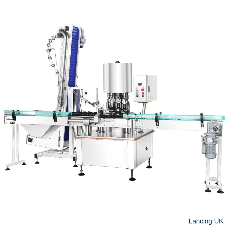
Closure compatibility
A small change in cap height, liner thickness, perforation design or neck-bead geometry can affect tamper band position and opening torque. When a project uses a decorated cap, trials should also check scuffing and lacquer performance.
For best results, treat the cap, bottle and machine as one system. Lancing UK can review samples and advise whether a semi-automatic, inline automatic or rotary multi-head ROPP capping system is the correct route.
Selection table
Use these checks to narrow the machine choice and avoid packaging compatibility problems.
| Area | Why it matters | Action |
|---|---|---|
| Cap diameter | Drives head tooling and roller geometry | Essential for machine configuration |
| Cap height | Affects top pressure, thread area and band position | Important for cap presentation and support |
| Liner type | Controls sealing behaviour and opening torque | Must suit product and bottle finish |
Process
A documented setup gives better repeatability and easier troubleshooting.
Confirm the closure drawing and bottle neck drawing.
Trial caps from the actual supplier batch when possible.
Check cap appearance before and after capping.
Measure torque and inspect tamper band bridges.
Document setup for repeat orders and future batches.
Related ROPP guidance
These pages cover machine range, automatic options, troubleshooting and the enquiry route for bottle and cap samples.
FAQ
No. The cap must be designed for the bottle neck finish and the capping machine setup.
They can if the cap finish, tooling or roller setup is not suitable. Trials should inspect printed and lacquered caps carefully.
Cap height affects liner compression, thread formation area and the position of the tamper-evident band.
Usually this requires change parts or head adjustments. The exact requirement depends on the machine and the cap range.
Send your cap size, bottle height, neck finish, samples and target output for practical advice.
Aluminium closure handling
The aluminium body is both a functional forming component and often a visible brand surface. Incoming condition, feeder contact, cap transfer, roller action and downstream handling can each affect the final appearance.
| Stage | Inspection | Control |
|---|---|---|
| Incoming supply | Dents, ovality, liner/insert position, band/bridges and decoration. | Identify supplier and lot; retain uncapped reference samples. |
| Bulk and feeder handling | Rubbing, impact, recirculation, chute pressure and misorientation. | Sample caps at feed stages and agree the acceptable marking standard. |
| Cap placement | Square seating, bottle centring and interference with inserts/pourers. | Control the transfer and reject uncertain caps before forming. |
| Thread and band forming | Roller marks, wrinkles, tears, thread definition, tuck and bridges. | Use approved tooling and small documented adjustments. |
| Finished-pack movement | Contact with guides, inspection equipment, coder or accumulation. | Trace post-cap marks separately from head or feeder marks. |
Use the liner guide to separate cosmetic finish from actual sealing evidence.
Use the feeding guide to validate decorated closures through the complete path.
Use the inspection plan to record incoming, post-feed and post-forming condition.
Include the closure drawing, liner/insert, decoration standard, supplier lot and intended bottle finish.